
Same box art as the 1/35th version.
This is my third Dragon model, and, like the other two so far, in 1/72. I happen to also have the 1/35 version of this same vehicle, again by Dragon. But I'm saving the foray into that larger scale for some future point. The Stug and Tiger that I previously made had full-colour photographically illustrated instructions. This one has the more traditional black and white line style directions, although the book is still a full colour affair.
This was the trickiest Dragon build so far, and not all of that for good reasons. I've found all the Dragon instructions, whilst very nicely presented, not quite as clear (or perhaps I ought to say idiot-proof?) as I would like. This set were even less easy to follow. One of the biggest issues on all the Dragon instructions is their use of compound steps. By that I mean a single picture into which several stages of construction have been compressed.
This causes issues with a lack of clarity - not helped in this instance by several other issues, which I'll go in to in due course - as it can be quite easy to miss something, or difficult to see things properly. The additional issues that further complicated things for me were: some steps that simply weren't given at all; some mis-numbered and/or missing parts; some confusing things in the diagrams themselves.
This causes issues with a lack of clarity - not helped in this instance by several other issues, which I'll go in to in due course - as it can be quite easy to miss something, or difficult to see things properly. The additional issues that further complicated things for me were: some steps that simply weren't given at all; some mis-numbered and/or missing parts; some confusing things in the diagrams themselves.

Can you see, above, the hole I refer to below?
Here are a few examples: 1) In the picture above, note the hole on the left-side of the lower casemate (on the left side of the tank, that is; the right side as you look at it in the pic. above), on the darker shaded angled section. In the instructions there's no hole there. Instead there's a curved protrusion. I found two similar looking parts on sprue A, and chose to use the part most closely visually matching the part in the pic. Although this part looks right, it wasn't included in the assembly instructions, nor was there any 'male' part (to go into the hole), or any other kind of location marking. So I had to more or less guess where it ought to go, the only guide being that it should obscure the hole!
Actually there were rather too many instances, I feel, of parts that would've benefitted from more clarity as to proper fit. The whole upper hull construction, which is comprised of five sub-assemblies - casemate, front deck, rear deck and left and right track- or mud-guards - is, despite a few alignment indicators, ripe for misalignment. Indeed, when I put it all together, and attached it to the lower hull, there were a number of places where the model was not achieving a snug fit. This can be seen in the above pic, where the upper and lower front hull sections meet, a visible gap widening as you scan from left to right.


Inner faces of the hatches, with some nice (if possibly redundant?) detail.
Outer faces of the same hatches.
Some nice but perhaps redundant detail is included on the rear hatch of the casemate. It's redundant chiefly because you'd have to destroy the inner detail in order to attempt to display it open. The two upper casemate hatches also annoyed me, due to the hinges, which are beautifully sculpted and cast, but do get in the way of a clean assembly. These can both be modelled open or closed. And if the larger rectangular hatch is modelled open, it has some supporting struts, and more of that nice (but this time less redundant) internal detail.

Case(mate) closed!
One reason I chose to model the casemate hermetically sealed was that there's no inner gun detail. Indeed, in relation to the gun, I was somewhat disappointed that this kit doesn't allow for any movement at all. As there are no inner casemate fixtures the equivalent of those on the front exterior, if you didn't glue the gun in position, it'd just drop into the hull! If you did model the hatches open, you might just be able to see the rear hatch detail (you'd have to model the entire rectangular hatch open - which isn't shown or suggested in the instructions - i.e. both sides open), but there'd either be no inner gun detail, and that you certainly would see, or else you'd need to scratch built it, along with any other desired interior detail.
All of these gripes, and I'm only just getting to my second point in my critique of what I hold to be rather duff instructions! 2) In the step within the instructions dealing with the open and closed options for the circular upper casemate hatch, close examination of the pics reveals that closed they are shown one way round, and open, the other. If the two halves were identical this would be immaterial. But they aren't. Surely the same part should be placed on the same side regardless of whether the hatch is to be open or closed?

The as yet unattached exhaust system that I screwed up somewhat.
3) This time I refer to the issue of what I'm calling 'compound' stages. At a certain point in the assembly I failed to spot that I needed to add a particular part. This resulted in a number of mistakes. First of all, when assembling the rear upper-deck area it didn't go together quite right, and second, my omission lead in turn to a real panic/bodge/hash when I started to assemble the exhaust elements pictured above. At present this whole assembly is, I believe, a bit wrong. I think some suitably thin slices of the right diameter sprue, or some plastic rod, will sort it (at some point!).
One small but simple instance of plain dumbness on my part, and therefore not something I have enumerated as a gripe, was forgetting to add the single lens periscope (I left out the binocular periscope altogether) until after I'd attached the casemate to the hull. How I missed that I don't know! Getting it into its proper position once the hull and casemate were joined together was a real challenge. Fortunately I hadn't put the hatches on, as I ought to have done had I followed the instructions to the letter. But I'd decided by this stage that the instructions were flawed enough to be departed from!
4) My fourth complaint is not about the instructions, but the model itself: most Dragon stuff I've built, including most of this kit as well, is superlatively well manufactured. There was an issue on this kit, however - at least for me as my model-making techniques currently stand - which is that several very delicate parts are attached to the sprue in such a way that removing them wrecked them. This happened to a number of parts. But the worst cases were the aerial, and the rear chassis wheel racks. All these components were very thin, and the sprue attachment points were too big/coarse.

The original plastic rear wheel racks. I believe I glued these the wrong way around. And perhaps I ought to have tried to add the spare wheels before fixing them to the hull?
I decided to snip off the aerial - which was irretrievably damaged anyway - with a view to perhaps replacing it, either with fine wire or some stretched sprue. That was easy. But the wheel-racks... Ach, mein giddy führer! did they ever cause me grief!? In another instance of lack of instructional clarity, I wasn't sure if I ought to add the spare wheels before attaching the whole sub-assembly to the rear-deck or afterwards. Actually this was a bit of a moot point anyway, for several reasons...

Note: only enough spare wheel parts to make two spares, not the full four. The darker grey wheels (from a different kit/brand) look right, but are too small, and none of the wheels fitted anyway!
Which brings me to point 5) There are sufficient inner-wheel parts (the nicely detailed inserts, shown in the pic. above) for the entire running gear, plus four spare wheels, but there are not the same number of actual wheels. There are 20 of the detailed inner-wheels, but only 18 of the full double outer-wheels! What gives? In the end this proved ultimately to be as much of a relief as it was a disappointment. I did try some road wheels from a Plastic Soldier spares set, but they were significantly smaller. And this is all pretty academic anyway, 'cause none of them fitted! Indeed, my attempts to make them fit simply destroyed the already weak and malformed plastic parts that comprised the storage frames.

Scratch-building wire replacements: having cut and bent all the elements, modelled on their plastic counterparts...
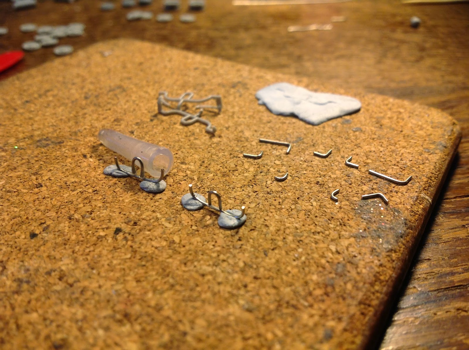
... gluing begins.
Rather than simply leave out these rather cool looking details, I decided I'd scratch-build my own. Rummaging around a bit I eventually rooted out some appropriately sized and shaped wire. The series of pictures above/below shows my slow and painful progress with making these. Making these took me many hours, and I wasn't even that pleased with how they were turning out. The biggest arse-ache was trying to fix the individual pieces together. I find super-glue immensely frustrating. It's guaranteed to glue together absolutely anything and everything except the bits I want to glue. And even when it does finally glue the the pieces I do want to glue together, it does so in the wrong positions, and usually with horrible blobby accretions of glue. Aaaaarrrrgh!!!!

What a nightmare it was...

... working with cyanoacrylate!
Next time I try this I must see if I can build similar parts using plastic rods. At least they'll glue easily! Bending wire is relatively easy - although getting the right shaped bends is harder - but gluing it is a real mother! I think the basic kit build took two three hours. It took just as long, poss even significantly longer, just to build those two g'damn wheel racks. I tried once again to add spare wheels. But still no dice! I took up modelling for pure pleasure. And most of the time that's just what it is. But trying to glue these wheel-bins. Sheesh... that was certainly purgatory, perhaps even hell!

Attaching whe wheel-storage racks.

Finally, several hours later... in situ.
Just as I started to worry I really was losing my mind, I finally finished the wheel-racks. I popped a few more tiny details onto the model, including one or two bits that broke off whilst I wrestled with gluing the wire, in the process noticing further discrepancies to do with missing or unused parts. And finally I sprayed the whole lot with a black undercoat. Having typed this, I'm gonna go have one last look. I do hope those pesky wheel racks look better with a lick of paint in 'em!?


Well, although this model is as yet unfinished, joining the ever-growing ranks of my WWII German armour pool that awaiting the eventual purchase of a dual-control airbrush, it time for a temporary verdict. Conclusion!? Well, this was certainly not as enjoyable a build as the previous two Dragon kits. They were magic. This is going to be, I hope, a decent enough tank, once finished. But it was, by comparison with the Stug IV or Tiger I, more tragic than magic. I do hope the 1/35 version is more enjoyable!
-----
Since posting this, point 6 occurred to me: of the six photo-etched parts this model contains, only two seemed essential. The other four all had plastic equivalents, and the two nicest photo-etched elements - triangular struts with holes in them (which in order to be used require the removal of plastic counterparts) - are more or less invisible by the time the models completed!
No comments:
Post a Comment